Rules Download
15th National College Student Intelligent Vehicle Competition Rules for Speed Racing Rules
Excerpts from Beacon Group Rules
Track
Analysis: Compared to other groups without specific track requirements, the “freedom” here emphasizes the importance of obstacle avoidance, as the vehicle might tilt or encounter other unexpected situations. The guidance methods include RF signals and sound signals, which will be analyzed below.

Competition Tasks
Analysis:
- Vehicle dimensions are restricted to within 30cm on each side.
- Main control MCU is restricted to the
Infineon TC26X
series microcontroller:- Infineon’s chip is a dual-core MCU (a first for us).
- The main frequency is 200MHz, which is relatively low.
- Competition format includes two stages: a preliminary qualification round and a head-to-head race.
- Due to the pandemic this year, the head-to-head race was canceled, and only the light-extinguishing speed was considered.
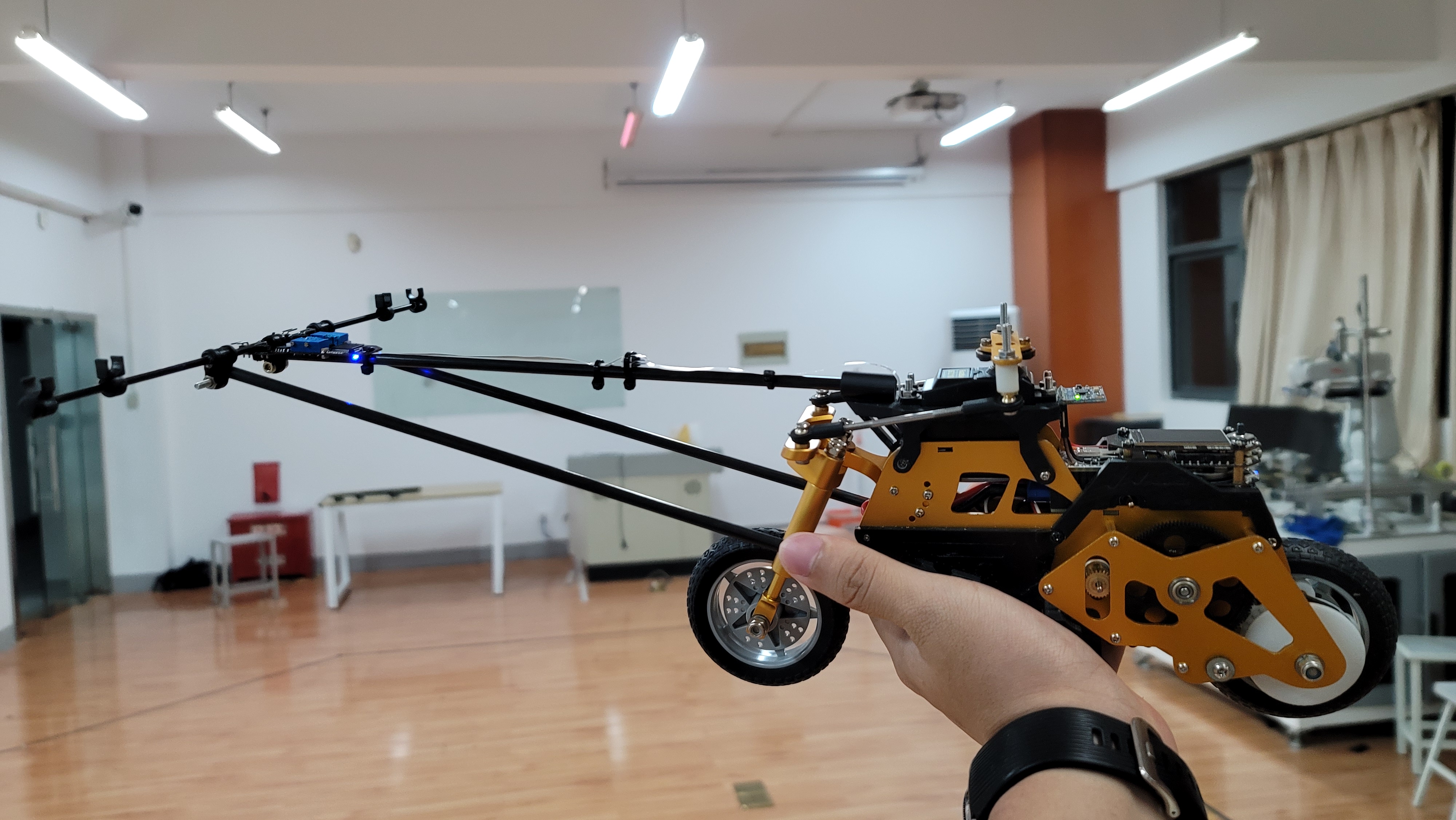
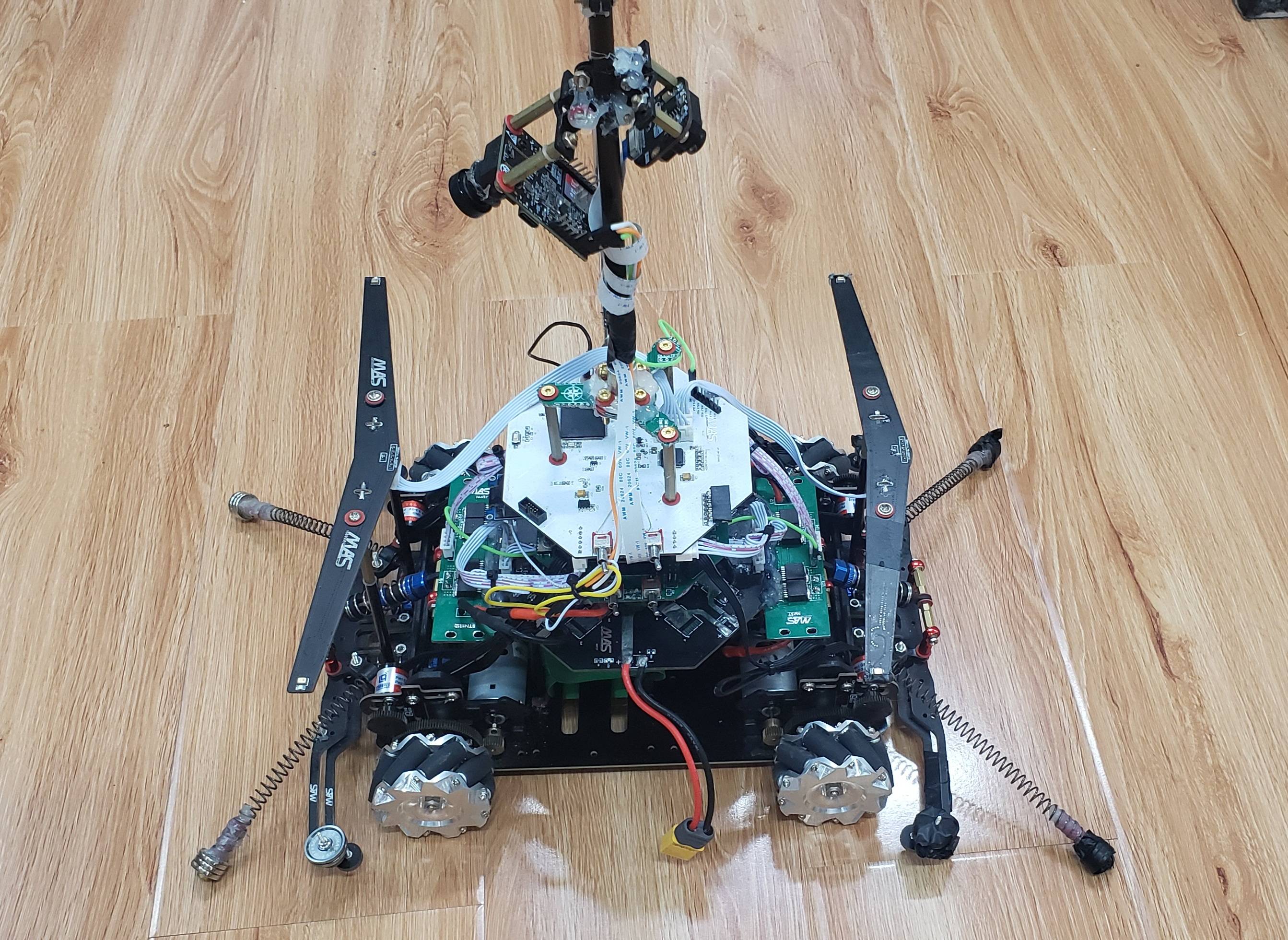
- Vehicle model: H model.
- The H model uses Mecanum wheels, enabling omnidirectional movement.
- Naturally, we chose the expensive diamond version of the H model, but due to special circumstances, we hadn’t received it by the end of July.
- RF signals are frequency-modulated Chirp signals ranging from 50Hz to 2000Hz, as shown below:
Solution Analysis
Existing solutions in the competition include, but are not limited to, the following.&
Special thanks to all the teachers for their creative ideas that inspired our solutions~:cherry_blossom:
According to the principle of sound distance measurement, the distance D
is given by:
$$
D=(t_{receive}-t_{send})*V_{sound}
$$
Assuming the sound undergoes only amplitude attenuation, time delay, and Gaussian white noise during transmission:
$$
f_{r}(t)=A\cdot f_{s}(t-t_{0})+n_{0}(t)
$$
By performing a cross-correlation operation between the received signal and the original transmitted signal:
$$
R_{r,s}(t)=\int_{-\infty }^{+\infty }f_{s}(\tau )\cdot f_{r}(\tau -t)d\tau
$$
The peak of the correlation result corresponds to the actual signal delay.
Solution 1: Cross-Correlation Operation Between FM Signals and MIC Signals
Solution Overview
This is the solution we are currently using.
The FM signal received by the RDA5807
and the audio signal captured by the microphone array are processed using cross-correlation operations.
Advantages and Disadvantages Analysis
- Advantages
- FM signals propagate in space as electromagnetic waves at the speed of light, making them suitable as reference signals.
- The speed of sound is approximately 340 m/s. By performing a cross-correlation operation to determine the peak index and combining it with the sampling rate fsample, the positioning accuracy can be calculated as Vsound/fsample.
- Offers a certain degree of fault tolerance, allowing precise positioning even if music is played near the microphone.
- Disadvantages
- High requirements for sound propagation: no echoes and minimal interference or noise.
- The RAM resources of the microcontroller are limited, supporting a maximum of only 2048 points for operations. This restricts the ability to improve accuracy by increasing the sampling rate.
- The speaker-microphone system is not a pure delay system, as it exhibits different amplitude-frequency characteristics and phase-frequency characteristics at different frequencies.
- Optimization Plan
- Use the FFT algorithm to convert the cross-correlation operation into frequency-domain conjugate multiplication and then solve the cross-correlation using IFFT. FFT (Fast Fourier Transform) reduces the time complexity of DFT (Discrete Fourier Transform) from O(N2) to O(NlogN). Additionally, FFT is more accurate than DFT due to reduced rounding errors.
- Replace the current
MAX9814
microphone receiver sold in most smart car stores with Knowles silicon microphones. Compared to electret microphones (conventional microphones), silicon microphones offer smaller size, better product consistency, and higher stability, making them more suitable for high-end devices. (Experimental results confirm that silicon microphones provide significantly more stable distance measurements than electret microphones.)


- To achieve a sharper peak in the cross-correlation function, the generalized cross-correlation method can be used, which involves whitening the input signal with a weighting function in the frequency domain. (Currently, the standard cross-correlation algorithm provides relatively stable results. Although there is some noise, the signal-to-noise ratio is within an acceptable range, with at most one value deviating. Whether to introduce the weighting function will be decided based on future circumstances.)
- Use the
TC264DA
chip. Compared to theTC264D
, the DA version includes hardware FFT and 512KB of EMEM storage space:- The hardware FFT supports a maximum of 1024 points, which is
basically useless. - Accessing the 512KB EMEM memory space takes three times as long as accessing the CPU’s internal memory.
- The hardware FFT supports a maximum of 1024 points, which is
- Increase the sampling period, effectively extending the sweep frequency duration. This can suppress the impact of environmental noise to some extent. However, the competitive nature of the contest limits us to collecting at most two cycles of signals. (Practical results show that the cross-correlation result from two cycles is significantly better than that from one cycle.)
MATLAB Simulation Results
The original signal did not use a frequency-modulated signal because I was lazy, but it’s roughly the same.
Program Results
Solution 2: Converting FM Signals and MIC Signals into Square Waves for Input Capture
Solution Overview
Both the RDA5807
and the silicon microphone convert FM signals into varying voltage signals, which are then read by the ADC to obtain the corresponding voltage values. At this point, a hysteresis comparator can be used to convert the sine wave signal into a square wave signal. Through input capture, only a small segment of the FM waveform is sampled to determine its frequency. Subsequently, the corresponding frequency waveform is located within the sound’s “square wave,” allowing the phase difference to be calculated.


It can be observed that the waveform is not ideal, as the $t_{pd}$ (Propagation delay time) is excessively large. However, the comparator being used is TI’s TL3201
, which, according to the chip datasheet, should theoretically have a delay of around 50ns. This issue will be investigated further when time permits.
Advantages and Disadvantages Analysis
- Advantages
- This method is very fast in solving the time difference, with the theoretical maximum time difference $\triangle t$ by:
$$
\triangle t=\frac{L_{max}}{V_{voice}}
$$
-
Disadvantages
- Low fault tolerance: If the microphone waveform corresponding to the FM frequency is not captured, the result will differ significantly. (This can be mitigated through pruning. For example, if the microphone frequency is found to be lower than the captured FM frequency, the FM signal can be recaptured.)
- Some frequency-modulated signals have amplitudes that are too small, making it impossible to trigger the comparator.
- The comparator is not ideal. In summary, the ideal is rich, but reality is harsh.
- Reducing the dead zone makes it highly susceptible to noise interference.
Solution 3: Pure Microphone Array Localization
Solution Overview
This is a simplified version of Solution 1, primarily utilizing the GCC-PHAT algorithm.


Solution 4: Using the AD8302 Phase Detector to Output Phase Information
This solution was discovered while lurking in a group chat. I’ll verify later to see if it’s feasible.